

| หากต้องการใบเสนอราคา / ใบแจ้งหนี้ ติดต่อได้ทาง LINE Official: @mikroelec |
 |
IM3318 three-phase energy metering module-voltage and current environmental protection electricity consumption monitoring electrical parameter acquisition module
| รหัสสินค้า | SKU-00819 |
| หมวดหมู่ | โมดูลวัดแรงดันและกระแสไฟฟ้า |
| ราคา | 450.00 บาท |
| สถานะสินค้า | พร้อมส่ง |
| ลงสินค้า | 9 ก.ย. 2563 |
| อัพเดทล่าสุด | 4 ต.ค. 2568 |
| จำนวน | ชิ้น |

รายละเอียดสินค้า
IM3318
Three-Phase Energy Metering Module
Product Series
| Product Series | Temperature Range | Operating Voltage | Package |
|---|---|---|---|
| IM3318 | -40℃~+85℃ | 3.3VDC | SMD18 |
Product Features:
- Single input power supply
- High precision electrical parameter measurement
- Provides AC voltage, current, power, power factor, frequency and other parameters
- Baud rate support 1200-9600kbps Default: 2400, even parity
- Provides voltage loss detection, voltage and current reverse phase sequence detection
- Provides Modbus protocol
- User-friendly, low product development cost
Product Applications:
- Motor protection
- Coal mining industry
- Power monitoring
- Petroleum and chemical industry
- Building automation
- Fire power supply monitoring
Product Model
| Product Model | Power Supply Voltage (Range) (VDC) | Quiescent Current (mA) | Default Baud Rate (kbps) | Parity Check Type | Default Modbus Address | Communication Interface |
|---|---|---|---|---|---|---|
| IM3318 | 3.3 (3.15-3.45) | 35 | 2400 | Even Parity | 01 | TTL |
Input Characteristics
| Parameter | Condition | Minimum Value | Typical Value | Maximum Value | Unit |
|---|---|---|---|---|---|
| Input Voltage | 3.3VDC Input Series | 3.15 | 3.30 | 3.45 | VDC |
| 5VDC Input Series | 4.75 | 5.00 | 5.25 | VDC | |
| Drive Current | TXD, RXD | -- | -- | 2 | mA |
| CON | -- | -- | 5 | mA | |
| Serial Interface | 3.3VDC Input Series | Only compatible with +3.3V standard UART interface | |||
| 5VDC Input Series | Only compatible with +5V standard UART interface | ||||
Analog Signal Characteristics
| Parameter | Condition | Minimum Value | Typical Value | Maximum Value | Unit |
|---|---|---|---|---|---|
| Voltage Sampling Signal | -- | 7 | -- | 265 | VAC |
| Current Sampling Signal | -- | 0 | -- | 5 | A |
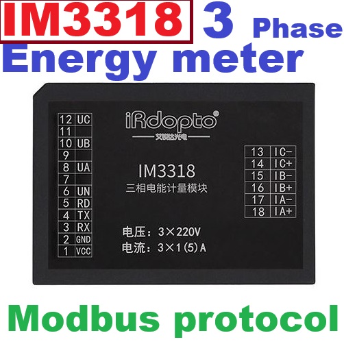
Pin Definition
| Pin Number | Pin Name | Characteristic | Function Description |
|---|---|---|---|
| 1 | VCC | Input | Module power supply pin. Operating voltage: 3.3V. This pin can be connected to 10UF/16V capacitor in parallel with 100NF/16V ceramic capacitor for decoupling |
| 2 | GND | Reference Ground | Digital power ground |
| 3 | RXD | Input | UART communication receive data pin, TTL level interface. Can be directly connected to user MCU UART |
| 4 | TXD | Output | UART communication transmit data pin, TTL level interface. Can be directly connected to user MCU UART |
| 5 | RD | Output | Currently not supported |
| 7,9,11 | NC | None | No connection. Recommended: leave floating |
| 6 | VN | Input | Voltage channel neutral line input port, can directly connect neutral line to pin |
| 8 | VA | Input | Voltage channel Phase A sampling input port. Direct three-phase Phase A |
| 10 | VB | Input | Voltage channel Phase B sampling input port. Direct three-phase Phase B |
| 12 | VC | Input | Voltage channel Phase C sampling input port. Direct three-phase Phase C |
| 13 | IC- | Input | Current channel Phase C negative current signal input terminal, port Imax 5A. Recommended circuit: Connect CT with ratio of 1000A/5A or below according to user load |
| 14 | IC+ | Input | Current channel Phase C positive current signal input terminal, port Imax 5A. Recommended circuit: Connect CT with ratio of 1000A/5A or below according to user load |
| 15 | IB- | Input | Current channel Phase B negative current signal input terminal, port Imax 5A. Recommended circuit: Connect CT with ratio of 1000A/5A or below according to user load |
| 16 | IB+ | Input | Current channel Phase B positive current signal input terminal, port Imax 5A. Recommended circuit: Connect CT with ratio of 1000A/5A or below according to user load |
| 17 | IA- | Input | Current channel Phase A negative current signal input terminal, port Imax 5A. Recommended circuit: Connect CT with ratio of 1000A/5A or below according to user load |
| 18 | IA+ | Input | Current channel Phase A positive current signal input terminal, port Imax 5A. Recommended circuit: Connect CT with ratio of 1000A/5A or below according to user load |
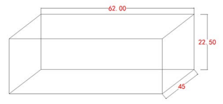
Dimension Drawing
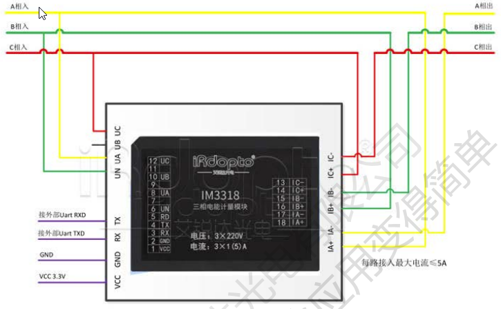
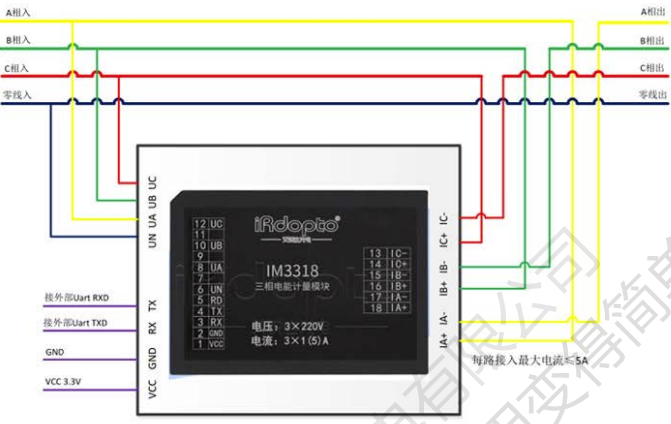
IM3318: three-phase four-wire, direct connection,
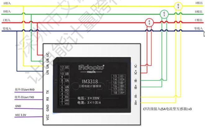
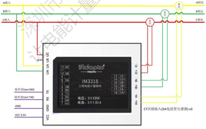
IM3318: three-phase four-wire, CT (Current Transformer) connection.
As shown in the figure, there are four wiring methods for IM3318: three-phase three-wire, three-phase four-wire, direct connection, and CT (Current Transformer) connection. The module wiring method is simple and reliable, convenient for users.
Note:
- Three-phase three-wire connection: Phase B of the voltage sampling circuit should be connected to the UN terminal of IM3318. IB current can be left floating.
- Direct connection allows a maximum current load of 5A. For loads exceeding 5A, use CT connection with external CT with secondary rated at 5A (50A/5A, 100A/5A, 200A/5A, 300A/5A, 1000A/5A, etc.). The current ratio can be set up to 200, with maximum testing capacity of 1000A current load.
Software Application Protocol
IM3318 supports Modbus-RTU protocol. For detailed protocol content, please refer to: MODBUS Protocol Description
Usage Precautions
- The firmware and protocol of IM3318 are built-in at the factory, making it convenient for users.
- When testing with IM3318, since the module measures high voltage equipment, pay attention to operation safety to avoid damaging the module and computer. The recommended schematic design includes communication isolation circuit for user reference.
- When testing Modbus protocol with IM3318, users can use our provided test software.
- Disclaimer: The information in this document is for reference only and does not constitute any invitation or commitment. iReader may modify the above information without prior notice.
Three-Phase Energy Collection Module Protocol Description
Meter Information and Parameter Setting Register Area
| Address | Parameter | Value Range | Data Type | Read/Write Property |
|---|---|---|---|---|
| 0000H | Module Information | High byte: Module model Low byte: Software version |
Word | R |
| 0001H | Basic Range | High byte: Basic voltage Low byte: Basic current |
Word | R |
| 0002H | Module Working Information | High byte: Module address Low byte: Baud rate *1 |
Word | R/W |
| 0003H | Current Ratio IBB | BCD code, Maximum setting 9999 times Default: 1 time |
Word | R/W |
| 0004H | Voltage Ratio UBB | BCD code, Maximum setting 9999 times Default: 1 time |
Word | R/W |
| 0005H | Energy Reset | High byte: Energy reset Low byte: Meter initialization *2 |
Word | R/W |
| 0006H | Electrical Working Status | Total 12 status *3 | Word | R |
| 0007H | Protocol | Tongliao Protocol: 5555 Other: AAAA |
Word | R/W |
| 0008H | Input Detection | High byte: 0x00 Low byte: Two-way detection *4 |
Word | R |
| 0009H | Parity Bit | High byte: 0x00 Low byte: Parity selection *5 |
Word | R/W |
| 000AH | Wiring Method | High byte: 0x00 Low byte: Wiring method selection *6 |
Word | R/W |
Notes:
*1 Baud Rate:
- 0x04: 1200
- 0x08: 2400
- 0x10: 4800
- 0x20: 9600
- Other values: 2400
*2 Set 0xAA: Clear related information
*3 Status Bit Definitions:
| Bit | Description |
|---|---|
| BIT00 | 1: Phase A voltage loss | 0: Phase A voltage normal |
| BIT01 | 1: Phase B voltage loss | 0: Phase B voltage normal |
| BIT02 | 1: Phase C voltage loss | 0: Phase C voltage normal |
| BIT03 | 1: Voltage reverse phase sequence error | 0: Voltage phase sequence normal |
| BIT04 | 1: Current reverse phase sequence error | 0: Current phase sequence normal |
| BIT05 | 1: At least one phase active power is negative | 0: All active power is positive |
| BIT06 | 1: At least one phase reactive power is negative | 0: All reactive power is positive |
| BIT07 | Undefined |
| BIT08 | Undefined |
| BIT09 | 1: Phase A in creep state | 0: Phase A in start state |
| BIT10 | 1: Phase B in creep state | 0: Phase B in start state |
| BIT11 | 1: Phase C in creep state | 0: Phase C in start state |
| BIT12 | 1: Combined phase active power is negative | 0: Combined phase active power is positive |
| BIT13 | 1: Combined phase reactive power is negative | 0: Combined phase reactive power is positive |
| BIT14 | Undefined |
| BIT15 | Undefined |
*4 Low byte bits 0 and 1 indicate input detection status. Example: 0x01 (0000 0001): Indicates first channel has data.
*5 Low byte: Parity selection
- 0x01: Odd parity
- 0x02: Even parity
- 0x03: No parity
- Default: 0x02
*6 Low byte: Wiring method selection
- 0x55: Three-phase four-wire
- 0xAA: Three-phase three-wire
| Address | Parameter | Value Range | Data Type | Read/Write Property |
|---|---|---|---|---|
| 0020H (High 16 bits) | Total Active Energy | 0--999999.99Kwh | Dword | R |
| 0021H (Low 16 bits) | ||||
| 0022H (High 16 bits) | Total Reactive Energy | 0--999999.99Kvar | Dword | R |
| 0023H (Low 16 bits) | ||||
| 0024H (High 16 bits) | Total Active Power | 0-9999.9999KW | Dword | R |
| 0025H (Low 16 bits) | ||||
| 0026H (High 16 bits) | Total Reactive Power | 0-9999.9999KVar | Dword | R |
| 0027H (Low 16 bits) | ||||
| 0028H (High 16 bits) | Phase A Active Energy | 0--999999.99Kwh | Dword | R |
| 0029H (Low 16 bits) | ||||
| 002AH (High 16 bits) | Phase A Reactive Energy | 0--999999.99Kvar | Dword | R |
| 002BH (Low 16 bits) | ||||
| 002CH | Phase A Voltage | 0-999.9V | Word | R |
| 002DH (High 16 bits) | Phase A Current | 0-99999.999A | Dword | R |
| 002EH (Low 16 bits) | ||||
| 002FH (High 16 bits) | Phase A Active Power | 0-9999.9999KW | Dword | R |
| 0030H (Low 16 bits) | ||||
| 0031H (High 16 bits) | Phase A Reactive Power | 0-9999.9999KVar | Dword | R |
| 0032H (Low 16 bits) | ||||
| 0033H | Phase A Power Factor | 0-1.000 | Word | R |
| 0034H (High 16 bits) | Phase B Active Energy | 0--999999.99Kwh | Dword | R |
| 0035H (Low 16 bits) | ||||
| 0036H (High 16 bits) | Phase B Reactive Energy | 0--999999.99Kvar | Dword | R |
| 0037H (Low 16 bits) | ||||
| 0038H | Phase B Voltage | 0-999.9V | Word | R |
| 0039H (High 16 bits) | Phase B Current | 0-99999.999A | Dword | R |
| 003AH (Low 16 bits) | ||||
| 003BH (High 16 bits) | Phase B Active Power | 0-9999.9999KW | Dword | R |
| 003CH (Low 16 bits) | ||||
| 003DH (High 16 bits) | Phase B Reactive Power | 0-9999.9999KVar | Dword | R |
| 003EH (Low 16 bits) | ||||
| 003FH | Phase B Power Factor | 0-1.000 | Word | R |
C Phase Electrical Parameters
| Address | Parameter | Value Range | Data Type | R/W Attribute |
|---|---|---|---|---|
| 0040H (High sixteen bits) | C Phase Active Energy | 0-999999.99 Kwh | Dword | R |
| 0041H (Low sixteen bits) | Dword | R | ||
| 0042H (High sixteen bits) | C Phase Reactive Energy | 0-999999.99 Kvr | Dword | R |
| 0043H (Low sixteen bits) | Dword | R | ||
| 0044H | C Phase Voltage | 0-999.9 V | Word | R |
| 0045H (High sixteen bits) | C Phase Current | 0-99999.999 A | Dword | R |
| 0046H (Low sixteen bits) | Dword | R | ||
| 0047H (High sixteen bits) | C Phase Active Power | 0-9999.9999 KW | Dword | R |
| 0048H (Low sixteen bits) | Dword | R | ||
| 0049H (High sixteen bits) | C Phase Reactive Power | 0-9999.9999 KVar | Dword | R |
| 004AH (Low sixteen bits) | Dword | R | ||
| 004BH | C Phase Power Factor | 0-1.000 | Word | R |
| 004CH | Grid Frequency | 0-99.99 Hz | Word | R |
Control Output Register Area
| Address | Parameter | Value Range | Data Type | R/W Attribute |
|---|---|---|---|---|
| 0000H | FF00: Output 1 0000: Output 0 | Word | W | |
| 0001H | FF00: Output 1 0000: Output 0 | Word | W | |
| 0002H | FF00: Output 1 0000: Output 0 | Word | W |
User Setting EEPROM Register Area
| Address | Parameter | Value Range | Data Type | R/W Attribute |
|---|---|---|---|---|
| 0000H | 0X00-0XFF | BYTE | R/W | |
| ... | 0X00-0XFF | BYTE | R/W | |
| 0010H | 0X00-0XFF | BYTE | R/W |
MODBUS Protocol Overview
This protocol uses a master-slave structure and half-duplex communication mode. Slave stations have their own address codes. The establishment and release of the communication link are both controlled by data frames sent from the master station.
1. Function Code "03": Read Multiple Registers
Master transmission message format:
| Master Transmission | Byte Count | Information Sent | Remarks |
|---|---|---|---|
| Slave Address | 1 | 01 | Sent to slave with address 01 |
| Function Code | 1 | 03 | Read Registers |
| Start Address | 2 | 0020 | Start address is 0020 |
| Data Length | 2 | 0002 | Read 2 registers (4 bytes total) |
| CRC Code | 2 | C5C1 | CRC code calculated by master |
Slave response message format:
| Slave Response | Byte Count | Returned Information | Remarks |
|---|---|---|---|
| Slave Address | 1 | 01 | From slave 01 |
| Function Code | 1 | 03 | Read Registers |
| Byte Count | 1 | 04 | 2 registers total 4 bytes |
| Register Data 1 | 2 | 0000 | Content of address 0020 |
| Register Data 2 | 2 | 0010 | Content of address 0021 |
| CRC Code | 2 | FBF5 | CRC code calculated by slave |
Product Datasheet
IM3318
Data Sheet
Three-Phase Energy Metering Module
2. Function Code "06": Write Single Register
Master transmission message format:
| Master Transmission | Byte Count | Information Sent | Example |
|---|---|---|---|
| Slave Address | 1 | 01 | Sent to slave with address 01 |
| Function Code | 1 | 06 | Write Single Register |
| Start Address | 2 | 0002 | Register address to write to |
| Write Data | 2 | 0108 | Corresponding new data |
| CRC Code | 2 | 28C5 | CRC code calculated by master |
Slave (PDM) response message format:
Identical to the message format and data content sent by the master.
MODBUS Protocol Examples
1. Set Module Address, Baud Rate
Master transmission data:
01 06 00 02 01 08 28 5C
01: Module address
06: Protocol function code
00 02: Setting register address
01 08: Setting data 01: Set address 08: Set baud rate (Refer to meter information and parameter settings for specific data)
08 5C: Data CRC check
Return data: 01 06 00 02 01 08 28 5C
2. Set Module Current Transformer Ratio
Master transmission data:
01 06 00 03 00 70 78 2E
01: Module address
06: Protocol function code
00 03: Setting register address
00 70: Setting data 0070: Indicates setting current transformer ratio to 70 times (BCD code) 01 00: Indicates 100 times
08 5C: Data CRC check
Return data: 01 06 00 03 00 70 78 2E
3. Read Module Total Active Energy
01 03 00 20 00 02 C5 C1
01: Module address
03: Protocol function code
00 20: Read register address
00 02: Number of module registers to read
C5 C1: Data CRC check
Return: 01 03 04 00 00 00 08 FB F5
01: Module address
03: Protocol function code
04: Number of register data bytes read (number of registers * 2)
00 00 00 08: Module register data read Indicates: Active energy 000000.08 Kwh
FB F5: Data CRC check
Note:
All data read is in BCD code format.
00 00 00 08 indicates: 000000.08
For example: If the voltage data read is 0x22 0x01, it indicates a voltage value of: 220.1V
4. Set User EEPROM Data
Transmit:
AA F6 00 00 10 00 01 02 03 04 05 06 07 08 09 0A 0B 0C 0D 0E 0F 5E 4D
AA: Module address
F6: Protocol function code
00 00: Setting register address
00 10: Setting data length
00 01 02 03 04 05 06 07 08 09 0A 0B 0C 0D 0E 0F: Setting data
5E 4D: Data CRC check
Receive:
AA F6 00 00 10 00 01 02 03 04 05 06 07 08 09 0A 0B 0C 0D 0E 0F 5E 4D
5. Read User EEPROM Data
Transmit:
AA F3 00 00 10 1D C8
AA: Module address
F3: Protocol function code
00 00: Read register address
00 10: Read data length
1D C8: Data CRC check
Receive:
AA F3 10 00 01 02 03 04 05 06 07 08 09 0A 0B 0C 0D 0E 0F D9 41
AA: Module address
F3: Protocol function code
00 00: Read register address
00 10: Read data length
00 01 02 03 04 05 06 07 08 09 0A 0B 0C 0D 0E 0F: Read data
D9 41: Data CRC check
6. Set Relay Output Data
Transmit:
01 05 00 00 FF 00 8C 3A
01: Module address
05: Protocol function code
00 00: Control relay register address
FF 00: Function code (FF00: Output 1 0000: Output 0)
8C 3A: Data CRC check
Receive:
01 05 00 00 FF 00 8C 3A
Appendix:
Gain Calibration (Module parameters at 220V, 2.5A, Power Factor 1.000)
Transmit:
AA 7A 22 00 22 00 22 00 25 00 25 00 25 00 05 50 05 50 68 F4
01: AA: Module address
7A: Protocol function code
22 00 22 00 22 00: Calibration voltage for A, B, C phases respectively (22 00: indicates 220.0V)
25 00 25 00 25 00: Calibration current for A, B, C phases respectively (25 00: indicates 2.500A)
05 50 05 50 05 50: Calibration active power for A, B, C phases respectively (05 50: indicates 0.550KW)
68 F4: Data CRC check
Receive:
AA 7A 22 00 22 00 22 00 25 00 25 00 25 00 05 50 05 50 68 F4
Phase Calibration (Module parameters at 220V, 2.5A, Power Factor 0.500L)
Transmit:
AA 9A 22 00 22 00 22 00 25 00 25 00 25 00 02 75 02 75 02 75 40 06
01: AA: Module address
9A: Protocol function code
22 00 22 00 22 00: Calibration voltage for A, B, C phases respectively (22 00: indicates 220.0V)
25 00 25 00 25 00: Calibration current for A, B, C phases respectively (25 00: indicates 2.500A)
05 50 05 50 05 50: Calibration active power for A, B, C phases respectively (05 50: indicates 0.550KW)
40 06: Data CRC check
Receive:
AA 9A 22 00 22 00 22 00 25 00 25 00 25 00 02 75 02 75 02 75 40 06
วิธีการชำระเงิน
ชำระเงินผ่านธนาคาร
ชำระเงินด้วยการ Scan QR


นโยบายการเปลี่ยนหรือคืนสินค้า
หมายเหตุ
ต้องไม่เสียหายอันเกิดจากใช้งานผิดพลาด ใช้ผิดวิธี ต่อไฟผิดขั้ว จ่ายไฟเกินกำหนด หรืออื่นๆที่ตรวจสอบแล้วไม่ได้เกิดจากความผิดพลาดจากการผลิตสินค้า

Member

อีเมล : mikroelec@gmail.com
TOP เลื่อนขึ้นบนสุด
