

| หากต้องการใบเสนอราคา / ใบแจ้งหนี้ ติดต่อได้ทาง LINE Official: @mikroelec |
 |
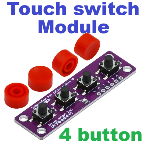
สวิตกด 4 ปุ่ม Touch four-button switch module compatible with Arduino Compatible Development Board Sensor Raspberry PI 51 MCU Suite


| รหัสสินค้า | SKU-02847 |
| หมวดหมู่ | โมดูลสวิตช์ |
| ราคา | 30.00 บาท |
| สถานะสินค้า | พร้อมส่ง |
| ลงสินค้า | 4 ธ.ค. 2567 |
| อัพเดทล่าสุด | 4 ธ.ค. 2567 |
| จำนวน | ชิ้น |
หยิบลงตะกร้า

รายละเอียดสินค้า
Product Description
Independent buttons are also called tap switches, which are used to push the working direction of the switch to match the working state, and the switch is closed and connected. When the pressure is withdrawn, the switch is disconnected, and its internal structure is realized by the change in the force of the metal bullet. We clearly find in the following four-pin circuit diagram that under normal circumstances, pins 1 and 2, 3 and 4 are connected; when we press the button, the four feet are connected; when the key is released, the normal state is restored. The key control can be realized by using digital I/O. The meaning of the digital I/O port is input and output. Now let's try to use the input function of the I/O in Arduino, that is, the function is to read the output value from an external device. In this experiment, we use a button and an LED to perform an experiment using a combination of input and output. Our key module will output a low level when the button is pressed and a high level when the key is released.
Pin Name Description
G GND (negative input power)
V VCC (positive input power)
1 digital signal pin
2 digital signal pins
3 digital signal pins
4 digital signal pins
Module parameters
Voltage: 3.3V/5V
Connection mode: 2.54mm pin row
Installation method: double screw fixing
วิธีการชำระเงิน
ชำระเงินผ่านธนาคาร
ชำระเงินด้วยการ Scan QR


ไมโครอิเล็กทรอนิกส์
098-xxxxxx-9
Accept All Banks | รับเงินได้จากทุกธนาคาร
นโยบายการเปลี่ยนหรือคืนสินค้า
หากสินค้าชำรุดหรือใช้งานไม่ได้ สามารถขอเปลี่ยนสินค้าได้ภายใน 7 วัน
หมายเหตุ
ต้องไม่เสียหายอันเกิดจากใช้งานผิดพลาด ใช้ผิดวิธี ต่อไฟผิดขั้ว จ่ายไฟเกินกำหนด หรืออื่นๆที่ตรวจสอบแล้วไม่ได้เกิดจากความผิดพลาดจากการผลิตสินค้า
หมายเหตุ
ต้องไม่เสียหายอันเกิดจากใช้งานผิดพลาด ใช้ผิดวิธี ต่อไฟผิดขั้ว จ่ายไฟเกินกำหนด หรืออื่นๆที่ตรวจสอบแล้วไม่ได้เกิดจากความผิดพลาดจากการผลิตสินค้า

Member
▲
▼
รายการสั่งซื้อของฉัน
รายการสั่งซื้อของฉัน
ข้อมูลร้านค้านี้

MikroElectronic
จำหน่ายอุปกรณ์อิเล็กทรอนิกส์ โมดูล เครื่องมือ และอุปกรณ์ต่างๆ arduino อาดูโน อะไหล่เครื่องใช้ไฟฟ้า อะไหล่อิเล็กทรอนิกส์ รับออกแบบวงจร เขียนโปรแกรมด้วยอาดูโน รับทำโครงงาน นักเรียนนักศึกษา ให้คำปรึกษาแก้ปัญหาโครงงาน ออกแบบและสร้างงานต้นแบบ ร้านตั้งอยู่ ซอยร่วมสุข ปทุมธานี สถานที่ใกล้เคียง ดอนเมือง สรงประภา ศรีสมาน นนทบุรี แจ้งวัฒนะ
เบอร์โทร : 0984829329
อีเมล : mikroelec@gmail.com
อีเมล : mikroelec@gmail.com
ส่งข้อความติดต่อร้าน
เกี่ยวกับร้านค้านี้
ค้นหาสินค้าในร้านนี้
ค้นหาสินค้า
สินค้าที่ดูล่าสุด
บันทึกเป็นร้านโปรด
Join เป็นสมาชิกร้าน
แชร์หน้านี้
แชร์หน้านี้
↑
TOP เลื่อนขึ้นบนสุด
TOP เลื่อนขึ้นบนสุด
สินค้าในตะกร้า ({{total_num}} รายการ)

ขออภัย ขณะนี้ยังไม่มีสินค้าในตะกร้า
ราคาสินค้าทั้งหมด
฿ {{price_format(total_price)}}
- ฿ {{price_format(discount.price)}}
ราคาสินค้าทั้งหมด
{{total_quantity}} ชิ้น
฿ {{price_format(after_product_price)}}
ราคาไม่รวมค่าจัดส่ง
รวมภาษีมูลค่าเพิ่มแล้ว
➜ เลือกซื้อสินค้าเพิ่ม