
| หากต้องการใบเสนอราคา / ใบแจ้งหนี้ ติดต่อได้ทาง LINE Official: @mikroelec |
 |

ร้านไมโครอิเล็กทรอนิกส์ จะหยุดทำการในวันที่ 25/10/2568 ถึง วันที่ 26/10/2568
หากสั่งซื้อสินค้าในวันดังกล่าว จะจัดส่งสินค้าให้ในวันที่ 27/10/2568ขออภัยในความไม่สะดวก.. |
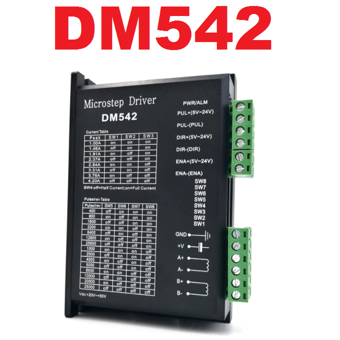
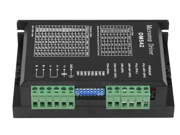
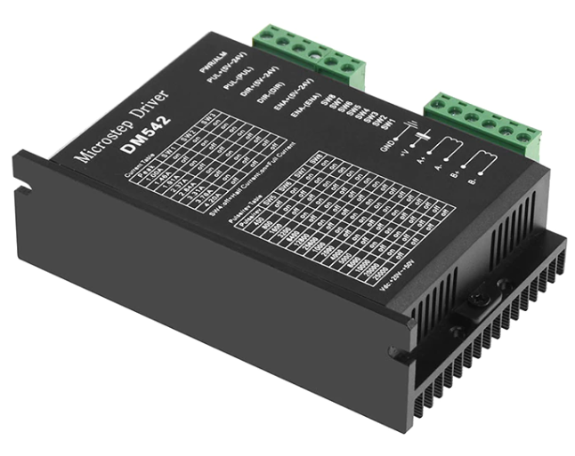
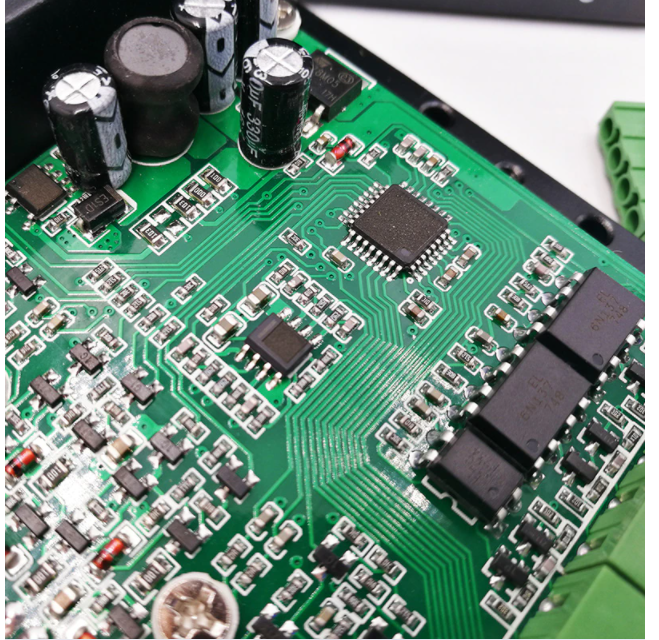
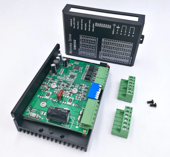
DM542 โมดูลขับสเต็ปปิ้งมอเตอร์ 20-50V 4.2A DSP digital 42/57/86 stepper motor driver engraving machine dedicated replacement 2M542/TB6600
| รหัสสินค้า | SKU-01785 |
| หมวดหมู่ | โมดูลขับมอเตอร์ (Motor Driver)/ อุปกรณ์ IO |
| ราคา | 450.00 บาท |
| สถานะสินค้า | พร้อมส่ง |
| ลงสินค้า | 2 พ.ย. 2564 |
| อัพเดทล่าสุด | 19 มี.ค. 2567 |
| จำนวน | ชิ้น |

รายละเอียดสินค้า
1. Electrical parameters:
1.Driver Integrated Overvoltage and overcurrent Protection
2.Input signal isolate
3.Bipolar constant chopping method
4.Power supply DC 20~50VDC (24~48VDC recommended)
5.Maximum drive current 4.2A
6.Output dial switch adjust
7.Low Speed ZERO Vibration with minimal noise
8.High anti-interference ability and reliability.
9.Power Consumption: Power Consumption: 80W; Within insurance: 6A
10.Temperature: temperature -10 ~ 45 ℃; Temperature -40℃~70℃
11.Humidity: non-condensing, condensation
12.Gas: Flammable Gas and Conductive Dust
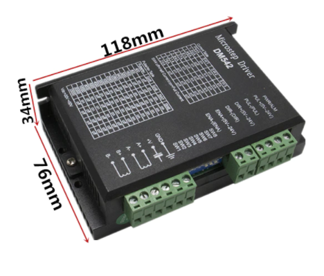
13.Weight: 200g
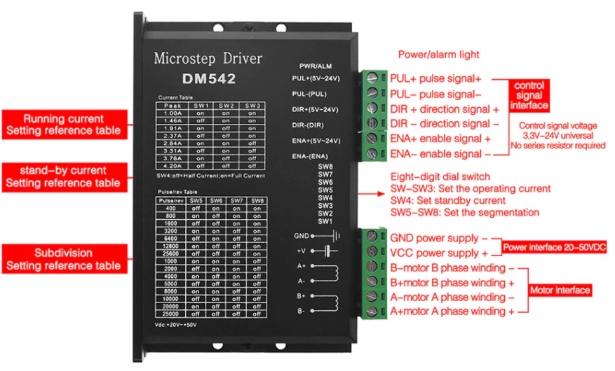
2.Control signal interface:
1. High definition control signal
PLS+: step pulse signal positive terminal or step positive pulse signal input positive terminal
PLS-: step pulse signal input negative terminal or step positive pulse signal input negative terminal
DIR+: Step direction signal positive terminal or reverse step pulse signal positive terminal
DIR-: step direction signal input negative terminal or reverse step pulse signal input negative terminal
ENA+: Offline enable signal reset input positive terminal
ENA-: Offline enable negative terminal input reset signal.
When the offline enable signal is valid, the drive fault is reset, any valid pulse is prohibited, the output power of the drive element is turned off, and the motor has no holding torque.
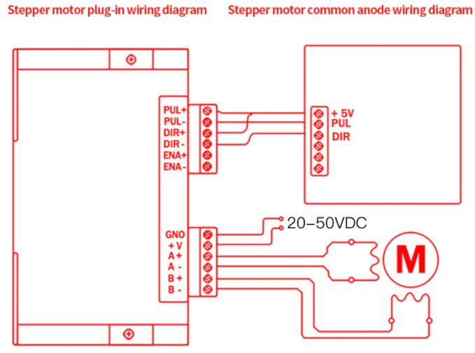
2.Control signal connection
The host computer control signal can have a high level performance or a low level. When effective high, connect the negative ends of all control signals together as the signal GROUND, when LOW, connect the positive ends of all control signals together as the common signal end. The circuit diagram interface is as follows:
Wire drive:
A complete stepper motor control system should include stepper drives, DC power supplies and controllers (pulse sources).
The following is a general system wiring diagram:
3. Set the current phase
In order to drive stepper motors with different torques, users can set the phase current. (effective value) of the drive amp through the DIP switches SW1, SW2, and SW3 on the drive panel, the corresponding output current of each switch position, and the pattern can be different. The corresponding output current value is different. See the table for details.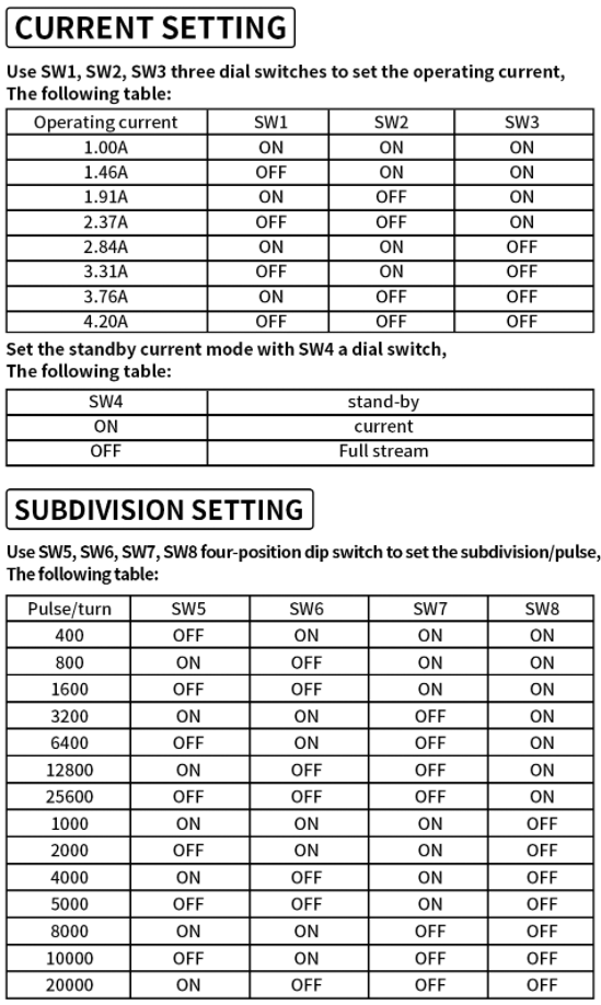
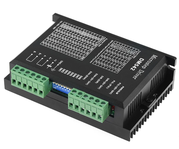
4. Interface:
1.V, GND: Connect the Driver Power Supply.
+V: DC positive, voltage DC 16~50V High current is 4.2A.
GND: Negative DC level
2. A + AB + B-: Connect the 2-Phase HYBRID Stepping Motor.
The connection between the driver and the 2-phase hybrid stepping motor uses four wires. The motor winding has a parallel and connection method, and the parallel connection method has good speed performance, but the driver current is large (1.73 times the motor winding current).
In series connection driver current is equal to motor winding current.

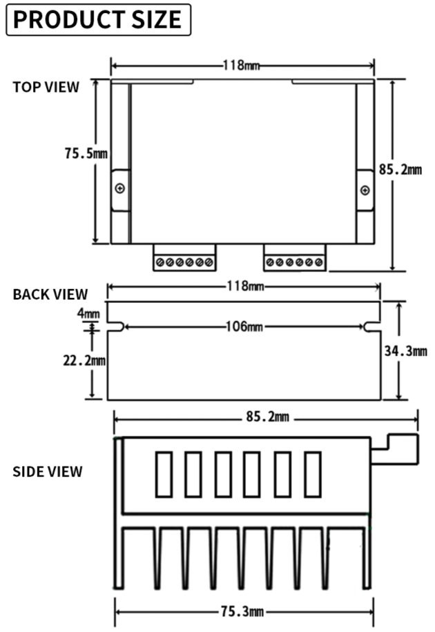
5. Installation:
There should be a space of 20mm around and should not be placed next to other heating equipment. Avoid Dust, Oil Mist, Excessive Corrosive Gas, Humidity and Strong Vibration.
Troubleshooting:
1. Status indicator light
RUN: Green, ON during normal use.
ERR: Red light, when a fault occurs, the circuit between the motor steps, G voltage and under voltage protection.
2. Failure and Troubleshooting
Solution: 1 check the power cord 2 increase the power supply voltage
Solution: Incorrect reset/correct motor connection.
Solution: Adjust the pulse and signal level.
Solution: Interchange two wires to connect and change direction setting.
วิธีการชำระเงิน
ชำระเงินผ่านธนาคาร
ชำระเงินด้วยการ Scan QR


นโยบายการเปลี่ยนหรือคืนสินค้า
หมายเหตุ
ต้องไม่เสียหายอันเกิดจากใช้งานผิดพลาด ใช้ผิดวิธี ต่อไฟผิดขั้ว จ่ายไฟเกินกำหนด หรืออื่นๆที่ตรวจสอบแล้วไม่ได้เกิดจากความผิดพลาดจากการผลิตสินค้า

Member

อีเมล : mikroelec@gmail.com
TOP เลื่อนขึ้นบนสุด
