

| หากต้องการใบเสนอราคา / ใบแจ้งหนี้ ติดต่อได้ทาง LINE Official: @mikroelec |
 |

ร้านไมโครอิเล็กทรอนิกส์ จะหยุดทำการในวันที่ 25/10/2568 ถึง วันที่ 26/10/2568
หากสั่งซื้อสินค้าในวันดังกล่าว จะจัดส่งสินค้าให้ในวันที่ 27/10/2568ขออภัยในความไม่สะดวก.. |
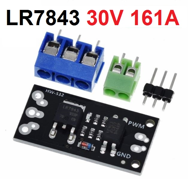
โมดูล LR7843 MOSFET 30V 161A คุมแบบแยกอิสระ Isolated MOSFET Module Replacement Relay Board


| รหัสสินค้า | SKU-01185 |
| หมวดหมู่ | โมดูลขับมอเตอร์ (Motor Driver)/ อุปกรณ์ IO |
| ราคา | 35.00 บาท |
| สถานะสินค้า | พร้อมส่ง |
| ลงสินค้า | 23 มี.ค. 2564 |
| อัพเดทล่าสุด | 27 ส.ค. 2567 |
| จำนวน | ชิ้น |

รายละเอียดสินค้า
Module features:
1. With optocoupler isolation, the control signal is isolated from the power supply of the controlled device, which greatly improves the interference.
2. Compatible with MCU and Arduino light control board, 3V or 5V signal
3. Start at high level, stop at low level, PWM speed regulation
4. It is widely used to control the start and stop of motors, solenoid valves and other tributary equipment
5. There are various specifications of MOS tubes to provide options,
E.g
FR120N: 100V 9.4A
LR7843: 30V 161A
AOD4184: 40V 50A
6. The signal input side can be soldered with terminal or pin, compatible with breadboard
7. The output can be soldered terminal or directly soldered
8. Module size 23mm X 16mm has two 2mm diameter screw holes, the hole spacing is 8mm
Module Connections
The module requires 3 connections. A logic signal to turn the MOSFET on/off; a DC power supply to power the device (load) being controlled and finally the load itself. Connectors are provided that can be soldered to be the board, but these connections can also be made by direct wiring if desired.
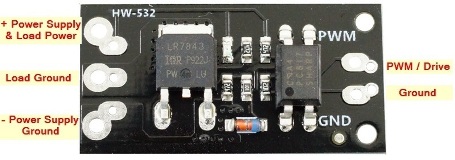
Logic Signal Connections: The 2-pin connector on the right side is for making connections to the MCU. It has two holes on 4mm centers which support a 2 position screw terminal as well as two holes on 0.1″ centers that can alternatively support a standard male header which may be handy in a breadboard setup. The pins are labeled PWM for the signal and GND for the signal ground.
DC Load Power Supply: is connected to the 3-pin screw terminals marked + / LOAD / – on the back of the module. The positive lead of the power supply connects to + and the ground connection is hooked up to –. The module supports a load power supply of 6-28VDC
Load: The load which is being driven is connected to the screw terminals marked + and Load on the back of the module. The positive lead of the load connects to the + terminal and the negative lead of the load connects to – terminal.
The signal ground and the load ground connections are not connected together on the module due to the optoisolator being used to provide isolation between the MOSFET power circuit and the MCU.
1 x 2 Screw Terminal / Header (Logic Signal Input)
- PWM = Signal input (active HIGH).
- GND = Signal ground
1 x 3 Screw Terminal (Load Power Supply Connections)
- + = Connect to power supply (6-28V) being used to power the load
- – = Connect to power supply ground
1 x 3 Screw Terminal (Load Connections)
- + = Connect to positive lead of load (motor, LEDs, fan, etc)
- LOAD = Connect to negative lead of load
Physical Mounting: There are two 2mm diameter holes at the signal end of the board spaced 12mm apart if it is desired to physically mount it.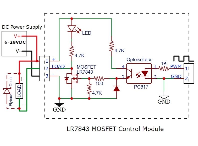
วิธีการชำระเงิน
ชำระเงินผ่านธนาคาร
ชำระเงินด้วยการ Scan QR


นโยบายการเปลี่ยนหรือคืนสินค้า
หมายเหตุ
ต้องไม่เสียหายอันเกิดจากใช้งานผิดพลาด ใช้ผิดวิธี ต่อไฟผิดขั้ว จ่ายไฟเกินกำหนด หรืออื่นๆที่ตรวจสอบแล้วไม่ได้เกิดจากความผิดพลาดจากการผลิตสินค้า

Member

อีเมล : mikroelec@gmail.com
TOP เลื่อนขึ้นบนสุด
